 Last updated 1/11/2006 This PC104 FAQ was written by Roger Arrick starting in the 1990's. It was hosted at Controlled.com for many years and is now here for preservation purposes. Many of the links here to external resources and email addresses have suffered bit rot and are now invalid.
-Roger Arrick, 
PC/104 - PC/104plus - EBX Embedded Systems
PC/104 Technical Questions and Answers
PC/104 systems are very similar to standard desktop PCs but with a different form factor. The name "PC/104" is derived from this likeness and the special stackable bus connector having 104 pins. These systems can be programmed with the same development tools used with full-size PCs which reduces the need and cost of custom development efforts. Although only about 4" x 4", PC/104 boards are very powerful for their size. PC/104 products are designed for minimal power consumption, small foot print, modularity, expandability, and ruggedness - basic needs of the embedded systems designer. Almost any type of module you can think of is now available for the PC/104 bus including CPUs, video controllers, network interfaces, sound I/O, data acquisition boards, and specialized interfaces. More than 200 vendors world-wide supply hardware, software, and engineering services to support the growing PC/104 standard. Would you like to see a typical PC/104 module. Return to the table of contents.
The PC/104-plus specification Defines the PCI addition to PC/104 including the connector details. The new connector has 120 pins with 2mm spacing, an overall width of about 2.4 inches, and occupies the space at the opposite side of the board from the existing bus connectors. The spec can be seen at http://www.controlled.com/pc104/consp5.html. Although vendors are finding it hard to place additional circuitry onto PC/104 boards that now have the plus PCI connector consuming space, they're being helped by the availability of video controllers, CPUs, gate arrays and other components with smaller footprints. The obvious result of PC/104-plus is increased performance for the ever-increasing demands of the embedded systems designer. Answer provided by Roger Arrick. Return to the table of contents.
PCI-104 is the terminology used for the PCI-only (32-bit PCI bus) specification within the PC/104 product family. PC/104 supports the ISA bus with a 104-pin connector, and PC/104-Plus supports ISA and PCI through separate connectors. PCI-104 eliminates the on-board support for the ISA bus, retaining only the 120-pin connector for PCI. ISA support may still be obtained through use of a PCI to ISA bridge. Because PCI is gradually replacing ISA as the bus of choice for device designs, the need for the ISA connector on the PC/104-Plus architecture is declining. The PCI-104 specification was adopted in 2003 by the PC/104 Consortium. The specification provides an industry standard for PC/104 footprint compatible devices that offer PCI, but not ISA bus connections. By not including the ISA connector, a small PC/104 format board regains space that can be used to provide additional functionality. Answer submitted by Michele Lukowski at VersaLogic Corp. Return to the table of contents.
Download the EBX specification here (225k PDF) Return to the table of contents.
What is a FAQ?
About Roger Arrick
Why do I do it?
Legal and Copyright information This FAQ is compiled and written by Roger Arrick of Arrick Publishing with contributions by vendors and users of PC/104 systems, among others. This document is Copyright (c) Roger Arrick - Arrick Publishing all rights reserved. Do not distribute this document without express permission from the author. Do not remove this notice. Contact the author via email at editor@controlled.com. Return to the table of contents.
We welcome contributions and comments from PC/104 users, vendors, engineers, programmers, and well, you get the idea - everyone. We're specifically looking for common questions asked about PC/104 systems. The Author will be allowed to place their name, company information, etc at the end of the contributed text. This gives companies a little P.R. to justify their effort. Naturally, self-promotion and marketing hype will not be allowed. After we receive your contribution, we'll do some minor editing, check for technical accuracy, add it to the FAQ, and notify you of your success. Sorry, we can't use information specific to a certain piece of equipment or software unless is offers insight on more universal issues. We hope you'll consider being a part of this noble effort. It'll look great on your resume! Send comments, articles, and information to the editor via email at editor@controlled.com. Electronic images can be sent as email attachments. Hardcopy can be sent to:
E-Zine of PC/104 Controlled Systems Return to the table of contents.
As you can imagine, the Internet is full of information about PC/104 and embedded systems. Here are a few links:
Web Sites
Frequently asked Questions available for downloading via FTP. You'll need an FTP (File Transfer Protocol) client or a browser that will let you download the file and save it.
You'll need a newsreader or a web browser with one to access newsgroups also known as USENET. This is where many questions get answered that are not covered in a FAQ. Most newsgroups have a FAQ associated with them.
Founded in 1991, the PC/104 Consortium is a member-supported, non-profit organization designed to support and promote PC/104 as an industry standard architecture for embedded PC applications. The Consortium maintains and publishes the PC/104 Specification, maintains an on-line resource guide, attends trade shows and promotes the PC/104 Embedded Systems Industry. Several categories of membership exist to meet a wide variety of participation levels. For more information on how you can become a member of the PC/104 Consortium please go to the On-line Consortium Information at Controlled.com. On-line Consortium Information at Controlled.com Contact the PC/104 Consortium at:
PO Box 78008 Return to the table of contents.
Initially released in 1992, the PC/104 standard document describes the technical details needed by Engineers and Programmers. Below you can download the current specification for PC-104, PC-104-Plus, and PCI-104.
Download the PC-104 V2.5 specification (200k PDF) The IEEE-P996 document describes the mechanical and electrical specifications for standard PC-style systems. Since PC/104 is based on this specification, we suggest you obtain a copy from IEEE at:
IEEE Standards Office
A listing of the PC/104 draft standard and others can be found on the IEEE on-line catalog at http://stdsbbs.ieee.org/products/catalog/drafts.html PC/104 differs from standard PC systems in the following ways:
Ways to use PC/104 Modules
Electrical Specifications Most signals have a reduced bus drive of 4ma which reduces power consumption and heat dissipation. Open collector signals must drive 330 ohm pull-ups for compatibility. Components driving MEMCS16, IOCS16, MASTER, and ENDXFR signals must be able to sink 20ma. Termination of the control signals is recommended to increase reliability. A network consisting of a 40 ohm resistor and a 30pf capacitor connected between each signal and ground is recommended by the P996 specifications. See the product database for a listing of companies that offer bus termination products. Interrupt sharing can be accomplished by following the recommendations mentioned in the P996 specification. Certain precautions must be taken to insure that signal specifications are not violated. See the P996 specification for additional information. Return to the table of contents.
Attending a show or exhibition can be an educational and fun experience. Most major cities are visited by a shows, conference, exhibit or seminar on a regular basis. The following list describes several shows that would be of interest to the embedded systems user:
The Real-Time Computer Show
Embedded Systems Conference
Embedded Computing Shows
IEEE Conference Listings A more complete list of shows can be found at the E-Zine of PC/104 Controlled Systems. Return to the table of contents.
Several industry trade journals cover issues related to embedded computing, here are a few:
RTC Magazine (Real-Time Computing)
PC/104 Embedded Solutions Magazine
Embedded Systems Programming Magazine Return to the table of contents.
Several book stores can be found on line that carry technical books including: On-Line Book Stores
We think the following books may be helpful to programmers, engineers and users of PC/104 embedded systems:
Indispensable PC Hardware Book
The Art of Programming Embedded Systems
Embedded Systems Programming In C and Assembly Language
Practical Guide to Real-Time Systems Development
Real-time Systems: Specification, Verification, and Analysis A more complete list of reading material can be found at the E-Zine of PC/104 Controlled Systems. Return to the table of contents.
How many PC/104 boards can be stacked? As with so many questions, the answer is "It Depends". Some PC/104 CPU manufacturers will only guarantee 5 or 6 cards in a stack, while others have tested their CPU modules with up to 10 boards or more. The answer depends on the amount of bus drive capability on the CPU as well as the bus loading of the add-on modules. A well-designed module presents a maximum of one load on any bus signal that it uses. A poorly designed one may leave out buffer ICs and present 2 or more loads on some lines, which limits the number of add-on modules that you can put on the stack without overloading the CPU. You will have to try your proposed configuration to know for sure. Ask the CPU manufacturer about their experience with their various CPU modules, and also ask the add-on module vendors about the bus loading of their modules. Sometimes, adding AC bus termination, as indicated in the PC/104 specification, will help ensure signal reliability on systems with large numbers of modules. Answer by Johnathan Miller at Diamond Systems Jdm@diamondsys.com. Sometimes there can also be physical limitiations to the number of PC/104 modules in a stack. Each module consumes about .6" of height. Vibration, space constraints and other factors of your specific application may be an issue. Addition offered by Roger Arrick.
How can you separate PC/104 cards without bending pins? The pin-and-socket bus of PC/104 offers one of the most reliable and rugged board connections available, yet PC/104 users often bend or damage these header pins when disassembling board stacks and separating modules. To prevent breaking pins, PC/104 board extraction tools can be used to easily and quickly disconnect system components. These kind of tools are commonly made of polypropylene plastic to prevent damage to static sensitive device. Users vertically position them next to a PC/104 or EBX circuit board and carefully lift all PC/104 pins out of the adjacent PC/104 socket. Answer provided by parvus Corporation. Return to the table of contents.
Are standoffs required when mounting PC/104 modules? PC/104 modules have traditionally been stacked together or onto baseboards using 0.60-inch nylon or aluminum standoff spacers between board mounting holes. While standoffs provide an economical mounting method, many PC/104 users have found them to be tedious and time-consuming to assemble or disassemble. As an alternative, PC/104 modules can be secured in railed card cages, which use four slotted aluminum rails and two steel end caps bolted together to support the PC/104 card stack. Holding up to 14 boards, card cages securely hold the four corners of each PC/104 circuit board and enables quick removal and replacement of defective modules or reorganization of the stack as it's being configured for thermal management, connector orientation, and cable routing. With cards installed, an entire card cage assembly can measure as small as four inches on a side. This method also enables shock/vibration isolators to be attached to the card cage for portable or otherwise rugged applications. Answer provided by parvus Corporation. Return to the table of contents.
Should a custom designed card be considered? Custom designs can provide precise system requirements by:
Most designs can be accommodated by 2-layer and 4-layer PCB's. Typical cost and delivery for a custom designed card in which a function specification is provided are as follows:
Concerning the number of cards usually required to justify the cost of the production prototypes: As an example, suppose two standard products are available that provide a system requirement using partial functions of each card. Suppose the combined costs of the cards is $375. A 2-layer design that combines these functions for n units might typically be: (1) Custom design for n cards = $1750 + (n-1) * $200 where $1750 is the proto and $200 is the additional cost/card. The two standard units would cost: (2) Standard products for n cards = n * $375 Equating (1) and (2) we find the break even cost occurs for n = 9. Thereafter, each card saves $175. In general, typical designs offer savings at 9 or 10 units. Answer submitted by John Hilburn at Microcomputer Systems. Return to the table of contents.
How do I add serial ports to my PC/104 system? PC/104 systems treat serial ports as do ISA bus systems. All you need is a serial communication module that is compliant with the PC/104 bus architecture. There are usually no special steps involved in configuring the port, other than the standard port address/IRQ jumper settings often found on the module. Once the module is plugged in the stack, any communications software will be able to access the module in the same way it would be accessed if it were an ISA bus serial port. Answer provided by Sealevel Systems. Return to the table of contents.
Configuring Windows 95/NT to recognize PC/104 serial module? You need to inform Windows of the new serial ports. The steps involved in doing this vary slightly depending on whether you are using 95 or NT. If you are using Win95:
If you are using NT, the process is even easier:
Return to the table of contents.
What serial communications interfaces are available for PC/104? Any interface that is available in ISA format. Product availability depends mainly on where you obtain your PC/104 modules. Some manufacturers provide products supporting multiple electrical interface i.e.(RS-232, RS-422, RS-485,... ). Following are descriptions of some of the common interfaces:
Return to the table of contents.
How do I perform synchronous serial communications on my PC/104 system? In order to perform synchronous communications, you will need a non-UART based communication module. A popular approach has been implemented by various manufacturers using the Zilog 85x30 family of serial communication controllers (SCC). These SCC based modules may or may not support Direct Memory Access (DMA) depending on the design. If the module does support DMA, then much higher data rates can be attained. Keep in mind that maximum data rates depend on factors including but not limited to CPU, electrical interface, line distance / quality, software efficiency, and whether the card supports DMA or not. Answer provided by Sealevel Systems. Return to the table of contents.
How can several serial ports share the same IRQ? There are two basic ways to do this. A simple but inefficient method is to set each port to the same IRQ and poll each port every time an interrupt is generated. Analogy - Imagine paging each of 8 employees offices to find out who paged you on the intercom. This is an example of polling. Each port/office gets checked but it takes time. The more efficient method is to have an Interrupt Status Port onboard the module. The interrupt status port tells you which port(s) generated the interrupt. An Interrupt Status Port (ISP) will provide greater efficiency/throughput when servicing multiple ports on a single interrupt line. The ISP is a read only 8-bit register that sets a corresponding bit when an interrupt is pending. Port 1 interrupt line corresponds with Bit D0 of the status port, Port 2 with D1 etc. The ISP is addressed at Base+7 on each port (Example: Base = 280 Hex, Status Port = 287, 28F etc.). This allows any one of the multiple locations to be read to obtain the value in the status register. All status ports on a single adapter are identical, so any one of the eight can be read. Analogy - Imagine the same office environment. This time, when you receive a page, your phone illuminates with the location of the office issuing the page. Instead of paging each office individually, you know that Bob in office #7 issued the page and simply page Bob back. These two analogies illustrate the advantages associated with shared interrupts and the Interrupt Status Port. Interrupt Status Port Example: The following indicates that Channel 2 has an interrupt pending.
Answer provided by Sealevel Systems. Return to the table of contents.
What is signal conditioning? More generally, signal conditioning is converting a signal from some transducer to whatever your receiving system needs. Frequently it's a matter of amplifying the microvolt or millivolt signals you get from (for instance) a strain gauge to the 10V span you need to get good resolution for your analog to digital converter. However, many transducers give you strange things that you have to convert. A tougher example is a Linear Variable Differential Transducer, which gives you a varying AC voltage (after you've given it a stable AC voltage). The voltage it gives you back varies in level with the position of the core, so you have to first convert that AC voltage to DC, then amplify scale it to fit into your ADC's span. Some transducers give you a current, which you must convert to a scaled voltage. These are all examples of signal conditioning, and you'll notice I haven't yet mentioned "cleaning up." You frequently want to clean the signal up, too, but that's usually incidental to the process. Most transducers give a far cleaner signal than you can use, so the best approach is to protect the signal you get from the transducer and convert and scale it directly, rather than trying to clean up a signal that's been contaminated by careless wiring. Answer submitted by John Hilburn at Microcomputer Systems. Return to the table of contents.
Can you extend the PC/104 bus height to accommodate tall components? Although the PC/104 specification calls for 0.60-inches (15mm) between stacked boards, some processor, hard drive and power supply modules exceed the standard height (i.e. due to heatsinks, fans or special ICs) and take up more than one card slot. These boards can in some cases be placed at the end of a board stack to avoid component interference, but this arrangement may not be optimal for prototype development or working with user cabling/packaging requirements. Another, more flexible method is to extend the height of the PC/104 bus by using double-height stack adapters. This type of low-cost PC/104 interconnection method provides a PC/104 system with the needed component clearance through an additional 16-bit pass-through header for all PC/104 bus signals. Such adapters have standard PC/104 board mounting holes and can be placed on top or bottom of any PC/104 module with a 104-pin and socket connector. Answer provided by parvus Corporation. Return to the table of contents.
Can you have multiple CPUs on a single PC/104 stack? It's important to remember that PC/104 is basically an ISA bus. This bus is intended to operate with a single CPU. There are many additional signals needed on a bus to handle the traffic on multi-CPU systems which PC/104 and ISA buses do not have. If you need multiple CPUs in a single system, consider having seperate PC/104 stacks that communicat using the serial port or a network card. It's often not necessary for multiple CPUs to have constant access to shared memory and I/O ports. Satelite processors can act as intelligent I/O controllers in order to off-load tasks from a main processor that's handling user I/O. Answer provided by Roger Arrick. Return to the table of contents.
What are the PC/104 connector pinouts? The name "PC/104" is derived from the fact that there are 104 pins on the two bus connectors which carry signals between modules. P1 has 64 pins and P2 has 40.
Each connector is a dual-row header having .1" pin spacing.
These connectors are offered by: ----------------------------------------------------------------------- PIN J1/P1 (ROW A) J1/P1 (ROW B) J2/P2 (ROW C) J2/P2 (ROW D) ----------------------------------------------------------------------- 0 0V 0V 1 -IOCHCHK 0V -SBHE -MEMCS16 2 SD7 RESET LA23 -IOCS16 3 SD6 +5V LA22 IRQ10 4 SD5 IRQ9 LA21 IRQ11 5 SD4 -5V LA20 IRQ12 6 SD3 DRQ2 LA19 IRQ15 7 SD2 -12V LA18 IRQ14 8 SD1 -ENDXFR LA17 -DACK0 9 SD0 +12V -MEMR DRQ0 10 IOCHRDY KEY -MEMW -DACK5 11 AEN -SMEMW SD8 DRQ5 12 SA19 -SMEMR SD9 -DACK6 13 SA18 -IOW SD10 DRQ6 14 SA17 -IOR SD11 -DACK7 15 SA16 -DACK3 SD12 DRQ7 16 SA15 DRQ3 SD13 +5V 17 SA14 -DACK1 SD14 -MASTER 18 SA13 DRQ1 SD15 0V 19 SA12 -REFRESH KEY 0V 20 SA11 CLK 21 SA10 IRQ7 22 SA9 IRQ6 23 SA8 IRQ5 24 SA7 IRQ4 25 SA6 IRQ3 26 SA5 -DACK2 27 SA4 TC 28 SA3 BALE 29 SA2 +5V 30 SA1 OSC 31 SA0 0V 32 0V 0VAnswer provided by Roger Arrick. Return to the table of contents.
Why are some PC/104 CPU boards bigger than PC/104 modules? Many CPU boards are larger than the standard PC/104 form factor in order to provide additional functions that would not fit on a smaller board. Doing so reduces the number of modules needed for a system and makes production and maintenance easier. Large boards like this often act as a carrier board for additional modules and sometimes act as complete systems by themselves. These CPUs still retain a PC/104 stacking connector for future expansion or for the addition of functions not found on the main board. Seek additional information on the new standard called "EBX". Answer provided by Roger Arrick. Return to the table of contents.
Is PC/104 supported by a large enough vendor base? PC/104 is definitely a standard with staying power. There are currently (Oct 2000) about 160 vendors who are members of the PC/104 consortium and many more that are not. Systems integrators and design firms world-wide are now designing, programming, and using PC/104 systems for real-world tasks every day. Selecting PC/104 as a platform for future product development is as safe a bet as can be made. Answer provided by Roger Arrick. Return to the table of contents.
What types of boards are offered for PC/104? Virtually every type of interface board imaginable is available in a PC/104 package. I've discovered the following types:
Answer provided by Roger Arrick. Return to the table of contents.
How can PC/104 systems address thermal management? PC/104 cards commonly support operational temperatures of 0�C to +70�C in standard modules and -40�C to +85�C in extended temperature-rated versions. As most temperature issues stem largely from a system's own CPU or power supply, heat sinks and/or fans can be used to maximize airflow and conductive/convective cooling. For PC/104 boards in a sealed enclosure, the use of PC/104 fan cards can effectively create a push-pull circular cooling pattern to eliminate failure-causing hot spots, as well as providing heat transfer to the outer enclosure. Typically available with dual ball-bearing fans mounted on a PC/104 form factor, fan cards can also incorporate onboard thermostats to monitor temperature in an intelligent way, based on multiple digital inputs, outputs, and connections to external temperature sensors. When heat transfer by airflow is not practical or sufficient, power supplies can be given a direct thermal connection to the body of the outer enclosure through low-profile conductive aluminum heatsinks. Externally mounted heatsinks, the length of the extrusion sides or enclosure end caps, can further dissipate heat away from the system. Answer provided by parvus Corporation. Return to the table of contents.
What type of power does PC/104 require? Like ISA the bus, PC/104 has 4 voltages available: +5v, -5v, +12v, -12v. The +5v supply is the most important and many PC/104 systems can run using it alone. Current levels range from 100ma up to many amps depending on the perpherials in the system. Vendors detail the power requirements for each module on their data bus. The other voltages: -5v, -12v, and +12v are often only needed at very small current - less than 50ma. Sound cards, video cards, and serial communication cards are the most common users of these voltages.
Communications boards
Disk drives
Linear and switching supplies
Battery operated
Packaging
Read those data sheets Answer provided by Roger Arrick. Return to the table of contents.
Driving Large Loads Many embedded systems must control large devices such as motors, lights, valves, etc. Driving such a load is normally done by attaching a digital output signal to a relay. The relay controls the large load from the small digital system in the same way that your car key switch controls your starter through a soleniod. There are both mechanical and solid-state relays on the market. Traditional mechanical relays rely on a coil which creates a magnetic field to cause the contacts to close or open. These coils normally require even more current than an digital output signal can provide requiring a buffer circuit in the form of a transistor. Mechanical relays can obviously wear out due to the moving parts involved. Contacts in the relay often arc creating a carbon deposit and electrical noise that can distrub near-by electrical equipment like the control computer.
Solid state relays
Digital I/O boards
Using the parallel printer port
Electrical spikes
Cable and connectors
Grounding Answer provided by Roger Arrick. Return to the table of contents.
What is the most common media used in Solid State Disks (SSDs)? The most common media in use today for creating solid state disks is Flash ROMs with some sort of BIOS extension (for bootable media) or installable device driver (for non-bootable data storage media). Most manufacturers provide a BIOS extension that will allow the user to use the standard DOS/Windows commands and file structure. Assuming the designer is using DOS, for example, the steps would be as follows: To make a bootable MS-DOS/Windows device: Type Format /s driveletter : and this will create an MS-DOS file structure as well as transfer the operating system to the SSD. To make a non-bootable device: Type Format driveletter : Notice that the /s command line switch is not used in this case so the Operating System is not copied onto the SSD. Answer contributed by Michael Peat at INSIDE Technology USA, Inc. . Return to the table of contents.
What about Solid State Disks (SSD) and a real-time operating systems? Many single board computer manufacturers provide additional software/firmware support for a variety of operating systems that are specific to their hardware. Another very simple way to implement an SSD for these types of applications is to use an IDE interface Flash Disk device. These are available from many of the single board computer manufacturers as well as third parties. These SSDs greatly simplify system development by using an IDE port on the single board computer. Thus, the user would follow the same steps as would be used in preparing any IDE hard drive for the operating system that is chosen. Answer contributed by Michael Peat at INSIDE Technology USA, Inc. . Return to the table of contents.
Year 2000 issues in embedded systems The so-called "year 2000" problem is caused when software uses only 2-digits to represent date codes in order to save space in memory and/or disk. The obvious problem occurs at the transistion between 1999 and the 2000. The year "1999" is stored as "99" and the year 2000 is stored as "00". Any calculations based on these 2, 2-digit values must take into account the roll over from 99 to 00 as being only 1 year. If the program does not contain special code to deal with this condition, then a calculation could return bad results.
An example
The solution
The world won't end For additional information you may want to visit Atlanta Year 2000 Users Group, and the Microsoft Year 2000 Resource center at www.microsoft.com/year2000/ Answer provided by Roger Arrick. Return to the table of contents.
Hand soldering PC/104 connector issues Is there any way to solder the stack through PC/104 bus connectors to a module PCB other than by hand soldering? The unique self-stacking capability of the PC/104 bus is made possible by the bus connectors. This arrangement is unique as the bus connectors are hermaphroditic interconnects i.e., a single bus connector functions as both plug and receptacle. The long .025 square tails of a bus connector on the solder side of an upper module plug into the receptacle side of the bus connector on a lower module. The basics of a reliable separable interconnection for signal level contacts require a noble metal finish (typically gold) on both plug and receptacle contacts. Therefore, any solder deposits on the mating portion of the connector tails would result in an unreliable connection. This rules out wave or localized solder fountain soldering. Solder preforms are an option to hand soldering. There are several drawbacks to using solder preform donuts; additional raw material cost, additional labor to install the loose donuts on each connector contact tail, retaining the donuts on the contact tails so that they don�t fall off in normal handling, and additional labor to manually apply flux. At this point soldering can be done by directing hot air to the contact tails or sending the connector through reflow. Reflow soldering is only possible if the connector housings is of a high temp SMT compatible material. PC/104 bus connectors have now been developed with the solder and flux pre-deposited on each contact at the factory. This is accomplished with solder and flux bearing clips that are designed to be economically applied with high speed automation and are also less expensive to manufacture that preform donuts. The connector housing is SMT compatible and oven reflow processing will yield top and bottom side filleted solder joints. Answer provided by Jim Zanolli of Teka Interconnection Systems Return to the table of contents.
The Five Steps to Data Acquisition
STEP 1 - IDENTIFY YOUR I/O SIGNAL TYPES
STEP 2 - CHOOSE A SIGNAL CONDITIONING METHOD
STEP 3 - SELECT THE APPROPRIATE DATA ACQUISITION I/O DEVICE
STEP 4 - CHOOSE THE APPROPRIATE CABLES FOR YOUR BOARD AND SIGNAL
CONDITIONING ACCESSORIES
STEP 5 - SELECT YOUR SOFTWARE PROGRAMMING METHOD Return to the table of contents.
Pressfit Style PC/104 Connectors Until recently, all long tail PC/104 connectors required a through hole solder application. While the few through hole components may be hand or wave soldered, this is extremely difficult and time consuming for the 104 gold plated connector pins. Solder preform donuts or solder and flux bearing clips allow for improvements in the soldering process by eliminating the hand soldering operation. They do however still require a high temperature solder process and close visual inspection. The only other option for applying a long tail stack through connector is with compliant pin technology. Adopted by the telecomm industry many years ago, pressfit technology has proven itself to be a cost effective alternative to soldering connectors to a board. Modern compliant sections deform to the plated through hole during the insertion process thus creating a reliable gas tight fit. Extensive laboratory testing and years of field operation have proven pressfit connector reliability in demanding environments. PC/104 connectors are now available with compliant pin technology. This allows for fast and simple insertion of the connectors into the finished boards, without any risk of uneven solder flow or contamination to the gold tails of the connectors. Fast and simple insertion of the connector into the through hole is accomplished by means of a flat rock tool and a simple bottom support fixture mounted on a hand press. The entire press-in process takes less then 5 seconds, with all positions maintaining equal resistance across the hole. Another added benefit of pressfit connectors, is the ability to rework the board by pressing the connector in a reverse process, allowing a replacement connector to be inserted. Answers provided by David Goodman at ept inc. Return to the table of contents.
What support is available for using Linux in PC/104 based systems? Most PC/104 boards that are made with standard desktop and laptop chipsets are going to work fine under Linux. Just watch out for the more obscure interfaces like PCMCIA and SCSI. In the case of "Real world" I/O interfaces, like analog, digital, motion control, etc., support will vary according to the manufacturer of the interface card. A whitepaper entitled "Using Linux in Embedded and Real Time Applications" is available at: http://linuxdevices.com/cgi-bin/article_view.cgi?artid=AT3611822672 For more information on using Linux in PC/104 based embedded applications, visit "the Embedded Linux Portal," at: http://www.linuxdevices.com Answers provided by Rick Lehrbaum at LinuxDevices.Com Return to the table of contents.
Collecting data from an IP address (Ethernet or Internet) directly into Access, Excel, etc. To collect data from an IP address directly into Windows applications (such as Excel or Access) you can write a custom application to communicate with the IP address. Because of the popularity of the Internet there are several inexpensive "programmer toolkits" that make it easy to add support for TCP/IP to any Windows application. If you are a hard core Windows programmer, you do not even need any tools; you can simply make API calls to the WinSock DLLs that come with Windows. You just need the specs for the API which are readily available on Microsoft's web site (http://www.microsoft.com). If you are a Visual Basic programmer, the Pro Edition of VB5 comes with an ActiveX control called the "MSWinSck.OCX" that makes it easy to add TCP/IP support to VB programs. If you are not a programmer TAL Tech makes a product called TCPWedge that allows you to collect data from practically any device on a TCP/IP network directly into any 32 bit Windows program including Excel, Access, etc. TCPWedge takes data from IP addresses, on any TCP/IP network, parses filters and formats the data and makes it available via DDE to other applications. It can also fully control devices over TCP/IP networks (Ethernet or Internet). It can support communications with up to 10,000 IP addresses from within Excel, Access and any DDE supporting Windows applications. For more information please visit http://www.taltech.com. Answers provided by Susan Rogers at TAL Technologies Return to the table of contents.
Making data from my RS232 device available at an IP address on a TCP/IP network There are "network protocol converters" available that will convert RS232 or RS485 serial data to TCP/IP network data. These protocol converters - also called terminal servers - make it possible to connect practically any device directly to any network. For example, you could attach RS232 device to an RS232 to TCP/IP converter and then connect the converter directly to a TCP/IP network and make it possible for any computer on the entire network to receive data from the RS232 device. Companies with RS232 to Ethernet converters include Lantronix (www.lantronix.com, model MSS1) and Z-World (www.zworld.com, EM1000). The same functionality can be acheived with TCP/com software, from TALtech Inc, and any Windows PC. TCP/com makes data from any RS232 port (up to 16 ports) available at IP addresses. A free down-loadable version of TCP/com is available on the Free Software page on TALtech's web site at www.taltech.com. Answers provided by Susan Rogers at TAL Technologies Return to the table of contents.
Are the four pads for the PC/104 board standoffs connected to ground or are they isolated? This issue is not defined in the specification. Therefore, it can (and has been) done either way by manufacturers. Even though there are valid reasons for either grounding or isolation, one will find a mix of both in boards available in the market today. Answers provided by Bob Burckle at WinSystems Return to the table of contents.
How many PC/104-Plus (PCI) modules can be placed on a stack? The maximum number of PC/104-Plus modules that can be placed on a stack is four. This is defined in section 3.2.2 of the PC/104-Plus Specification (version 1.2). However, the number of the boards on the stack may be less due to the number of PCI devices on the base CPU board. For example, a board based upon the Intel 430TX can directly support a maximum of 4 devices. If the base CPU board has the video and ethernet controllers included, then the maximum number of PC/104-Plus modules on a stack is two. Answers provided by Bob Burckle at WinSystems Return to the table of contents.
Mixing 3.3V and 5V signal levels The PCI bus and PCI on-board devices on many CPUs typically use 3.3V signaling (they drive the bus to 3.3V levels which are valid for either 3.3V or 5.0V receivers) and are 5.0V signal tolerant (they can receive either 3.3V or 5.0V signals). Some of the PCI signals are often pulled-up to 5.0V with a resistor. This means your module should be designed with components that are 5V tolerant. The ISA bus and ISA bus peripherals on a CPU card are different. The ISA bus is driven with 5.0V drivers, thus any board attached to the ISA bus must be 5.0V tolerant. However, the ISA bus receivers will accept either 5.0V or 3.3V signals. So the short answer to the question is "yes" an add on module which produces only 3.3V signals will work fine if it is also "tolerant" of 5V signals. Answers provided by Kristin Allen at VersaLogic Corp. Return to the table of contents.
How can I interface ISA and PC/104 products? While PC/104 and ISA PC cards are compatible electrically, they have different physical dimensions and different connectors - a pin/socket header versus a card edge. Using a PC/104 to ISA bus adapter card, which integrates both kinds of connectors, the two form factors can have a direct bus-to-bus interface and operates at full PC/AT system speeds without software modification or wait states to communicate. Developers can use these kinds of bus adapters to inexpensively develop and test PC/104 modules on an ISA-based computer or add an inexpensive ISA card to a PC/104 card stack when testing design concepts. Answer provided by parvus Corporation. Return to the table of contents.
What tools are available to debug/troubleshoot PC/104 boards? PC/104 bus line diagnostics boards and POST error code boards can be used to identify system failure points and provide a dynamic view of real-time bus activity. An alternative to traditional ohm-meters, diagnostics boards report bus line status through a series of LED indicators, each assigned to a specific bus signal. Similarly, POST boards display a two-digit hexadecimal code corresponding to the failure point for a PC-compatible BIOS' Power-On-Self-Test (POST) tasks. Answer provided by parvus Corporation. Return to the table of contents.
What alternative is there to stacking PC/104 cards? While PC/104 modules are typically stacked on top of each other, they can also be placed on off-the-shelf or custom baseboards. Such boards may include multiple PC/104 headers to enable PC/104 cards to be stacked on adjacent PC/104 buses rather than on top of each other. For height restrictive applications, this mounting method is especially useful. Four PC/104 boards mounted on a "quad motherboard" with four PC/104 headers measures less than 1.30" in height, as compared to 2.8" for four vertically stacked PC/104 modules. Answer provided by parvus Corporation. Return to the table of contents.
How can I connect more than two Ethernet products? PC/104 systems with multiple processors or peripherals that have Ethernet interfaces can use a PC/104 Ethernet switch or hub board to be networked together. Fast Ethernet and 10BaseT switches or hubs are available with auto-MDI-MDIX network installation and up to five auto-configurable 10/100 transceiver ports. Ethernet connections are made through either onboard RJ-45 jacks or via right-angle Molex connectors that can be used to mount RJ-45 jacks in a faceplate, endcap or enclosure. Answer provided by parvus Corporation. Return to the table of contents.
How can I eliminate constant polling of my I/O and still get the data? Polling of Digital Inputs from contact closures or other events can be a processor intensive operation. Some PC/104 boards include a useful feature called event detection, or change of state detection. This eliminates the need for constant polling and reduces processor overhead by generating an interrupt whenever any of the inputs change. Then the ISR (interrupt service routine) polls the inputs one time to collect the snapshot of the data. This feature typically adds to the cost of the board, but overall system performance can be significantly improved. In systems where the data is changing rapidly, this feature isn't as useful. Answer submitted by Marty Wingett (info@accesio.com) at ACCES I/O Products, Inc. Return to the table of contents.
http://www.controlled.com/pc104faq End of the PC/104 Embedded Systems FAQ Document
|

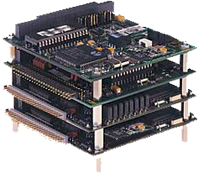 PC/104 is a standard for PC-compatible modules (circuit boards) that can
be stacked together to create an embedded computer system. These types
of systems are often found in factories, laboratories, and machinery
to provide programmable control of a complex system.
PC/104 is a standard for PC-compatible modules (circuit boards) that can
be stacked together to create an embedded computer system. These types
of systems are often found in factories, laboratories, and machinery
to provide programmable control of a complex system.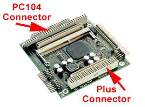 PC/104-plus is basically a PCI (Peripherial Component Interface) bus addition to
the PC/104 standard. PCI gives peripherial devices more direct access
to the CPU which can greatly improve system performance.
PC/104-plus has arrived just in time to serve video controllers, processors, and
other high-throughput devices while maintaining backward compatability with PC/104.
PC/104-plus is basically a PCI (Peripherial Component Interface) bus addition to
the PC/104 standard. PCI gives peripherial devices more direct access
to the CPU which can greatly improve system performance.
PC/104-plus has arrived just in time to serve video controllers, processors, and
other high-throughput devices while maintaining backward compatability with PC/104.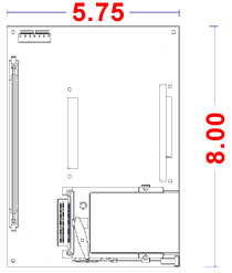 EBX (Embedded Board eXpandable) is a standard that defines a non-backplane embedded
controller that can contain PC/104-plus modules and other devices.
The standard was designed by Ampro and Motorola and is based on the "Little Board"
form factor from Ampro.
EBX boards are 8" x 5.75" which is large enough to contain a highly integrated
system and yet maintain expandablilty using additional PC/104-plus modules.
EBX (Embedded Board eXpandable) is a standard that defines a non-backplane embedded
controller that can contain PC/104-plus modules and other devices.
The standard was designed by Ampro and Motorola and is based on the "Little Board"
form factor from Ampro.
EBX boards are 8" x 5.75" which is large enough to contain a highly integrated
system and yet maintain expandablilty using additional PC/104-plus modules.
Return to Roger Arrick's Computer Menu