24 June 2023
 Click images for larger view
D-sub connectors are common on vintage computers. Here's some quick information about how they're named and what they are used for.
In the 1950's the D-subminiature connector was introduced and became popular on computers for communications. The pins are small and designed to carry low-voltage signals, not for power, although pins can carry an amp or more.
Wire size used for cables having D-Sub connectors is typically 24AWG stranded but sometimes even smaller. Anything bigger would work but would be a waste since not much current is being passed.
D-Sub connectors on cables typically have a hood piece that the connector fits into. The hood covers up internal wiring and offers a strain-relief for the exiting cable. Hoods usually have a screw or thumb screw on each side that allows for secure mounting to a chassis-mount D-Sub which has female threaded standoffs sometimes called jack screws. The thread size is usually 4-40.
D-Subs were very common on small computers of the 70s and through the 90s until replaced by USB and other types of smaller and cheaper connectors.
The words Pin and Contact are used interchangeably here.
The first letter is D to indicate a D-Subminiature connector.
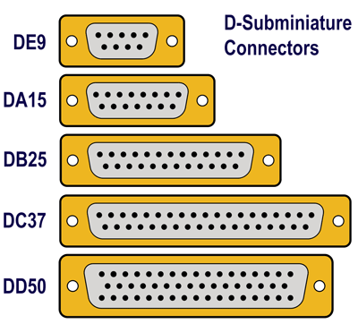
The second letter indicates the physical shell size - A, B, C, D, E. The smallest is E, followed by A, B, C, D in size order - I guess E was added after the initial sizes were introduced.
The next numbers indicate the number of contacts.
Sometimes a suffix added to indicate gender, M=male, F=female, or P=plug(male), S=socket(female).
The gender of a connector is determined by the contacts/pins of a connector, not the outer shell or housing. Male contacts go INTO female contacts. Some connectors like D-Subs have contacts of one gender but a shell of another. A male DB25 connector for example, has 25 male pins, but the female shell goes INTO the male shell.
General connector terminology is that a plug is male and a socket is female. In this picture, the top connector is male.
If you look very carefully on the back of a D-Sub you'll usually see tiny numbers for each pin. The pin numbering is usually 1-n across the top, then the next row, and so on. This means that when using flat cable the pin numbers will not match up to dual-row headers which have odd pin numbers across the top and even across the bottom.
Later there became a need for more contacts in a smaller space so several high-density versions were introduced. The most popular is 15 contacts in an E shell typically used with 9 contacts, so this would be called a DE15. The DE15 was used for VGA monitors on IBM-compatible PCs. I don't know why they didn't put a 16th contact on it, there's room.
When the IBM PC hit the market in 1981 it used D-Subs in several places for different interfaces, here's a quick run-down:
DE9 Female was used as the interface to monitors, both color (CGA) and monochrome, and later EGA.
DB25 Female was used as the parallel printer port. The other end of the cable is a 36 pin male 'Centronics' style connector for the printer. Basically a 36 pin 'Centronics' connector wouldn't fit well on the IBM adapter card rear panel, and it's expensive. If you plug an RS-232 device such as a modem into the parallel port it will damage the port because RS-232 typically uses +/-12 volt signals and the printer port is 5V circuitry.
DB25 Male was used as the RS-232 serial port. The other end of the cable was usually a male that connected to a female DB25 on a modem or a printer.
DA15 Female was used as the joystick port.
DC37 Female was used as the external floppy disk expansion port.
Later, serial ports began using a DE9 male instead of a DB25 male because it was smaller and only 9 signals were needed anyway. When VGA monitors were introduced, they used a DE15 which is a 15-pin high-density version of the DE shell used for the DE9.
Notice how the connector size and gender is used to prevent the user from accidentally plugging a device into the wrong port which could cause catastrophic results since some ports use different signal levels.
All this stuff is on the webs, no need to duplicate it here.
It's common for people to talk about the very popular 9 pin D-Sub connector as a DB9. This error comes from the initial popularity of the 25 pin DB25 connector that was used for printers and modems and terminals for decades. But it's not right, the 9 pin D-Sub has an E size shell, so it should be called DE9.