 Last updated 10/16/2008 This STD Bus FAQ was written by Roger Arrick starting in the 1990's. It was hosted at Controlled.com for many years and is now here for preservation purposes. Many of the links here to external resources and email addresses have suffered bit rot and are now invalid.
-Roger Arrick,
STD Bus Questions and Answers
STD bus began in 1978 with the initial 8-bit STD Bus specification created by Mostek and Pro-Log, now called STD-80. In the earily years, the STD bus was second only to IBM PC's ISA bus in popularity. At one point there were more than 100 vendors of STD bus products globally. The STD bus gained popularity because of its rugged construction, relatively small card size, industrial grade components with wide temperature range combined with low power consumption. These features lead to success in applications such as power and chemical plants, factory automation, medical equipment, and heavy machinery control. Eventually 16-bit data transfers were added to the STD-80 using a multiplexing scheme. Some vendors created minor variations to the bus for specialized purposes such as taking advantage of a new processor or to increase transfer rates. In the late 80's, Ziatech (Now owned by Intel and not producing STD/STD32 products) built upon the STD-80 8-bit specification and introduced STD32 which added 16-bit and 32-bit data paths while allowing backward compatibility with 8-bit systems. This was accomplished using a fancy bus connector similar to that of the EISA bus where pins on the bus connector make contact with different board pins depending on the features of the card. Currently, STD-80 and STD32 system popularity is slowly being replaced by newer technology such as the stackable PC104 systems, various incarnations of the PCI bus, VXI bus and others. Still, several core vendors exists along with other many smaller vendors that continue to make STD bus products. A large base of applications still exist in the marketplace which require maintainence and upgrades. From a software standpoint, STD-80 and STD32 systems run various real-time operating systems, popular operating systems such as MSDOS, Windows and Unix, or simply custom code written for a specific application without an underlying operating system. Processors range from the ancient Intel 8-bit 8080 to newer x86 generation processors, and even motorola 680XX and other types. Answer provided by Roger Arrick.
Answer provided by Roger Arrick.
The STD Bus has many features that offer advantages over other bus architectures.
Mature technology proven to work in many applications
Hundreds of thousands of systems running right now
Large card counts possible
Plenty of CPU power
Easy access to cards
Plenty of vendors
Very rugged
The Challenge Answer provided by Roger Arrick.
What is a FAQ?
About Roger Arrick
Why do I do it?
Legal and Copyright information This FAQ is compiled and written by Roger Arrick of Arrick Publishing with contributions by vendors and users of STD Bus systems, among others. This document is Copyright (c) Roger Arrick - Arrick Publishing all rights reserved. Please do not distribute this document without express permission from the author. Please do not remove this notice. Contact the author via email at editor@controlled.com.
We welcome contributions and comments from STD bus users, vendors, engineers, programmers, and well, you get the idea - everyone. We're specifically looking for common questions asked about STD bus systems. The Author will be allowed to place their name, company information, etc at the end of the contributed text. This gives companies a little P.R. to justify their effort. Naturally, self-promotion and marketing hype will not be allowed. After we receive your contribution, we'll do some minor editing, check for technical accuracy, add it to the FAQ, and notify you of your success. Sorry, we can't use information specific to a certain piece of equipment or software unless is offers insight on more universal issues. We hope you'll consider being a part of this noble effort. It'll look great on your resume! Send comments, articles, and information to the editor via email at editor@controlled.com.
As you can imagine, the Internet is full of information about STD Bus and embedded systems. Here are a few links:
Web Sites
Frequently asked Questions available for downloading via FTP. You'll need an FTP (File Transfer Protocol) client or a browser that will let you download the file and save it.
You'll need a newsreader or a web browser with one to access newsgroups also known as USENET. This is where many questions get answered that are not covered in a FAQ. Most newsgroups have a FAQ associated with them.
STD-80 Specification Section 1 (3meg) These are links to the STD32 Group:
STD32 Short-Form Specification (~250K)
Also, check the IEEE Standards Association at:
http://standards.ieee.org
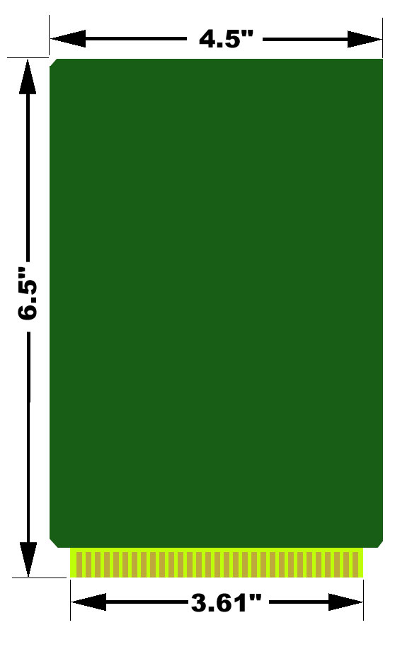
IEEE Standards Office Would you like to see a mechanical drawing of an STD Bus card?
STD-80 Specification Overview Each STD-80 card is 6.5" tall, 4.5" wide, .062" thick. The minimum spacing between each card in the card cage is .5" with .625" being typical. The bus connectors have 56 pins (28 on each side) on .125" centers. Card keying is provided to prevent upside-down insertion. Most STD-80 systems run on +5VDC only, but the bus also has pins defined for +12VDC, -12VDC for use with analog and other circuitry, along with a special battery voltage source. A typical power supply will deliver 5-10 amps on the +5VDC rail and much less on the +/-12 rails. A typical card cage will have 3-20 slots or even more and often are designed to fit in an EIA 19" rack. On high-integration STD bus cards which don't require other cards for support functions, it's possible to have a single board system without a backplane but only a single bus connector to supply power. From an electrical viewpoint, the STD-80 bus is designed with Intel's x86 processors in mind. That doesn't completely exclude the use of other processors, but does make it more complex to make them work due to differences in memory access timing, interrupt handling, etc. The bus is a simple single-master setup where the other cards are slaves designed to talk to a single processor. There is an 8-bit bidirectional data bus, 16-bit address bus, and various control pins used to control memory, I/O, interrupts, reset, etc. See the specification document for details about signal timing and drive levels. Additionally, special methods are defined for 16-bit data access and 24-bit address spaces. These expanded modes are accomplished with double 8-bit data transfers, and by multiplexing the new address bits on top of existing address and data pins.
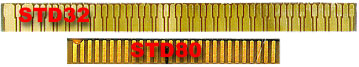
STD32 Specification Overview STD32 retains backward compatibility with STD-80 8-bit and 16-bit systems by using a special connector scheme like that found on MicroChannel and EISA buses. The total pin count increases from 56 to 136. See the STD32 specification for details about the new signal timing, extended cycles, board modes and new feature definitions. Answer provided by Roger Arrick.
Attending a show or exhibition can be an educational and fun experience. Most major cities are visited by a shows, conference, exhibit or seminar on a regular basis. The following list describes several shows that would be of interest to the embedded systems user:
The Real-Time Computer Show
Embedded Systems Conference
Embedded Computing Shows
IEEE Conference Listings A more complete list of shows can be found at the E-Zine of STD Bus Controlled Systems.
Several industry trade journals cover issues related to embedded computing, here are a few:
RTC Magazine (Real-Time Computing)
Embedded Systems Programming Magazine
Several book stores can be found on line that carry technical books including: On-Line Book Stores
We think the following books may be helpful to programmers, engineers and users of embedded systems:
Indispensable PC Hardware Book
The Art of Programming Embedded Systems
Embedded Systems Programming In C and Assembly Language
Practical Guide to Real-Time Systems Development
Real-time Systems: Specification, Verification, and Analysis A more complete list of reading material can be found at the E-Zine of STD Bus Controlled Systems.
What's the maximum number of STD boards in a card cage? It depends on both the drive capacity of the CPU board and the loading of the other boards. It's not uncommon for systems to have 20 or more cards, and it's also common to see small systems with only a couple of cards. Systems with high-integration CPU boards can consist of a single card. Answer provided by Roger Arrick.
Should a custom designed card be considered? Custom designs can provide precise system requirements by:
Most designs can be accommodated by 2-layer and 4-layer PCB's. Typical cost and delivery for a custom designed card in which a function specification is provided are as follows:
Concerning the number of cards usually required to justify the cost of the production prototypes: As an example, suppose two standard products are available that provide a system requirement using partial functions of each card. Suppose the combined costs of the cards is $375. A 2-layer design that combines these functions for n units might typically be: (1) Custom design for n cards = $1750 + (n-1) * $200 where $1750 is the proto and $200 is the additional cost/card. The two standard units would cost: (2) Standard products for n cards = n * $375 Equating (1) and (2) we find the break even cost occurs for n = 9. Thereafter, each card saves $175. In general, typical designs offer savings at 9 or 10 units. Answer submitted by John Hilburn at Microcomputer Systems.
What is signal conditioning? More generally, signal conditioning is converting a signal from some transducer to whatever your receiving system needs. Frequently it's a matter of amplifying the microvolt or millivolt signals you get from (for instance) a strain gauge to the 10V span you need to get good resolution for your analog to digital converter. However, many transducers give you strange things that you have to convert. A tougher example is a Linear Variable Differential Transducer, which gives you a varying AC voltage (after you've given it a stable AC voltage). The voltage it gives you back varies in level with the position of the core, so you have to first convert that AC voltage to DC, then amplify scale it to fit into your ADC's span. Some transducers give you a current, which you must convert to a scaled voltage. These are all examples of signal conditioning, and you'll notice I haven't yet mentioned "cleaning up." You frequently want to clean the signal up, too, but that's usually incidental to the process. Most transducers give a far cleaner signal than you can use, so the best approach is to protect the signal you get from the transducer and convert and scale it directly, rather than trying to clean up a signal that's been contaminated by careless wiring. Answer submitted by John Hilburn at Microcomputer Systems.
What are the STD Bus connector pinouts? The STD-80 spec defines 56 bus pins.
STD bus systems are aging but there are still several dozen suppliers globally.
Many of them are committed to provided STD bus products for the long haul.
Answer provided by Roger Arrick.
Answer provided by Roger Arrick.
Many STD Bus systems only need +5VDC, but some cards require +/-12VDC also.
Especially the ones that contain analog circuitry.
The amount of current needed will depend on the cards used but could
be as high as 10 amps or more on the +5 rail.
Linear and switching supplies
Packaging
Read those data sheets
Answer provided by Roger Arrick.
Many embedded systems must control large devices such as motors,
lights, valves, etc. Driving such a load is normally done by
attaching a digital output signal to a relay. The relay controls
the large load from the small digital system in the same way
that your car key switch controls your starter through a soleniod.
There are both mechanical and solid-state relays on the market.
Traditional mechanical relays rely on a coil which creates
a magnetic field to cause the contacts to close or open.
These coils normally require even more current than an digital
output signal can provide requiring a buffer circuit in the
form of a transistor. Mechanical relays can obviously wear
out due to the moving parts involved. Contacts in the relay
often arc creating a carbon deposit and electrical noise that
can distrub near-by electrical equipment like the control computer.
Solid state relays
Digital I/O boards
Using the parallel printer port
Electrical spikes
Cable and connectors
Grounding
Answer provided by Roger Arrick.
The most common media in use today for creating solid state
disks is Flash ROMs with some sort of BIOS extension
(for bootable media) or installable device driver (for non-bootable
data storage media).
Most manufacturers provide a BIOS extension that will allow the user to
use the standard DOS/Windows commands and file structure. Assuming
the designer is using DOS, for example, the steps would be as follows:
To make a bootable MS-DOS/Windows device:
Type Format /s driveletter : and this will create an MS-DOS file
structure as well as transfer the operating system to the SSD.
To make a non-bootable device:
Type Format driveletter : Notice that the /s command line
switch is not used in this case so the Operating System is not copied onto the SSD.
Answer contributed by Michael Peat
at INSIDE Technology USA, Inc. .
Many single board computer manufacturers provide additional
software/firmware support for a variety of operating systems
that are specific to their hardware.
Another very simple way to implement an SSD for these types of
applications is to use an IDE interface Flash Disk device. These
are available from many of the single board computer manufacturers
as well as third parties. These SSDs greatly simplify system
development by using an IDE port on the single board computer.
Thus, the user would follow the same steps as would be used in
preparing any IDE hard drive for the operating system that is chosen.
Answer contributed by Michael Peat
at INSIDE Technology USA, Inc. .
The so-called "year 2000" problem is caused when software uses only
2-digits to represent date codes in order to save space in
memory and/or disk.
The obvious problem occurs at the transistion between 1999 and
the 2000.
The year "1999" is stored as "99" and the year 2000 is stored as "00".
Any calculations based on these 2, 2-digit values must take into account
the roll over from 99 to 00 as being only 1 year.
If the program does not contain special code to deal with this
condition, then a calculation could return bad results.
An example
The solution
The world won't end
For additional information you may want to visit
Atlanta Year 2000 Users Group,
and the Microsoft Year 2000 Resource center at
www.microsoft.com/year2000/
Answer provided by Roger Arrick.
STEP 1 - IDENTIFY YOUR I/O SIGNAL TYPES
STEP 2 - CHOOSE A SIGNAL CONDITIONING METHOD
STEP 3 - SELECT THE APPROPRIATE DATA ACQUISITION I/O DEVICE
STEP 4 - CHOOSE THE APPROPRIATE CABLES FOR YOUR BOARD AND SIGNAL
CONDITIONING ACCESSORIES
STEP 5 - SELECT YOUR SOFTWARE PROGRAMMING METHOD
To collect data from an IP address directly into Windows applications (such as Excel or Access) you can write a custom
application to communicate with the IP address. Because of the popularity of the Internet there are several inexpensive
"programmer toolkits" that make it easy to add support for TCP/IP to any Windows application. If you are a hard core Windows
programmer, you do not even need any tools; you can simply make API calls to the WinSock DLLs that come with Windows. You just
need the specs for the API which are readily available on Microsoft's web site (http://www.microsoft.com). If you are a Visual
Basic programmer, the Pro Edition of VB5 comes with an ActiveX control called the "MSWinSck.OCX" that makes it easy to add TCP/IP
support to VB programs.
If you are not a programmer TAL Tech makes a product called TCPWedge that allows you to collect data from practically any device
on a TCP/IP network directly into any 32 bit Windows program including Excel, Access, etc. TCPWedge takes data from IP addresses,
on any TCP/IP network, parses filters and formats the data and makes it available via DDE to other applications. It can also
fully control devices over TCP/IP networks (Ethernet or Internet). It can support communications with up to 10,000 IP addresses
from within Excel, Access and any DDE supporting Windows applications. For more information please visit http://www.taltech.com.
Answers provided by Susan Rogers
at TAL Technologies
There are "network protocol converters" available that will convert RS232 or RS485 serial data to TCP/IP network data. These
protocol converters - also called terminal servers - make it possible to connect practically any device directly to any network.
For example, you could attach RS232 device to an RS232 to TCP/IP converter and then connect the converter directly to a TCP/IP
network and make it possible for any computer on the entire network to receive data from the RS232 device. Companies with RS232
to Ethernet converters include Lantronix (www.lantronix.com, model MSS1) and Z-World (www.zworld.com, EM1000).
The same functionality can be acheived with TCP/com software, from TALtech Inc, and any Windows PC. TCP/com makes data
from any RS232 port (up to 16 ports) available at IP addresses. A free down-loadable version of TCP/com is available on the Free
Software page on TALtech's web site at www.taltech.com.
Answers provided by Susan Rogers
at TAL Technologies
http://www.controlled.com/std End of the STD Bus FAQ Document
|

 The STD32 standard was created in the late 80's by Ziatech who was a dominate player in the STD-80 marketplace.
STD32 adds many new features to the 8-bit STD-80 standard including 16-bit and 32-bit data paths,
larger memory maps, multiple bus-masters, burst transfers, better interrupt handling, etc.
Backward compatibility with 8-bit cards is accomplished using special bus connectors that
are capable of handling both types of boards using a pin-interleave technology that is similar to the EISA bus and MicroChannel Bus.
The STD32 standard was created in the late 80's by Ziatech who was a dominate player in the STD-80 marketplace.
STD32 adds many new features to the 8-bit STD-80 standard including 16-bit and 32-bit data paths,
larger memory maps, multiple bus-masters, burst transfers, better interrupt handling, etc.
Backward compatibility with 8-bit cards is accomplished using special bus connectors that
are capable of handling both types of boards using a pin-interleave technology that is similar to the EISA bus and MicroChannel Bus.
Return to Roger Arrick's Computer Menu